
Re-inventing the wheel is a futile and time-consuming
process for countries like India, especially when there are a select few friendly,
highly industrialised countries that are more than willing to share their
expertise with India’s military-industrial entities and co-developing re-engineered,
customer-specific weapon systems that are required in large numbers by India’s
armed forces. Such a business practice thus cuts short the gestation timeframe
required for fielding advanced weapons on multiple platforms, since all their R
& D challenges have already been overcome before, and all that is required
to be done is to customise or re-engineer them for complying with the
qualitative requirements of their respective Indian end-users. Three such
weapons that are now under co-development comprise the Nirbhay family of land-attack
cruise missiles (LACM) and the BrahMos-NG supersonic multi-role cruise missile (MRCM)
being co-developed with Russia’s JSC MIC NPO Mashinostroyenia (NPOM), and the
smart anti-airfield weapon (SAAW) being co-developed with Israel’s RAFAEL
Advanced Defence Systems.

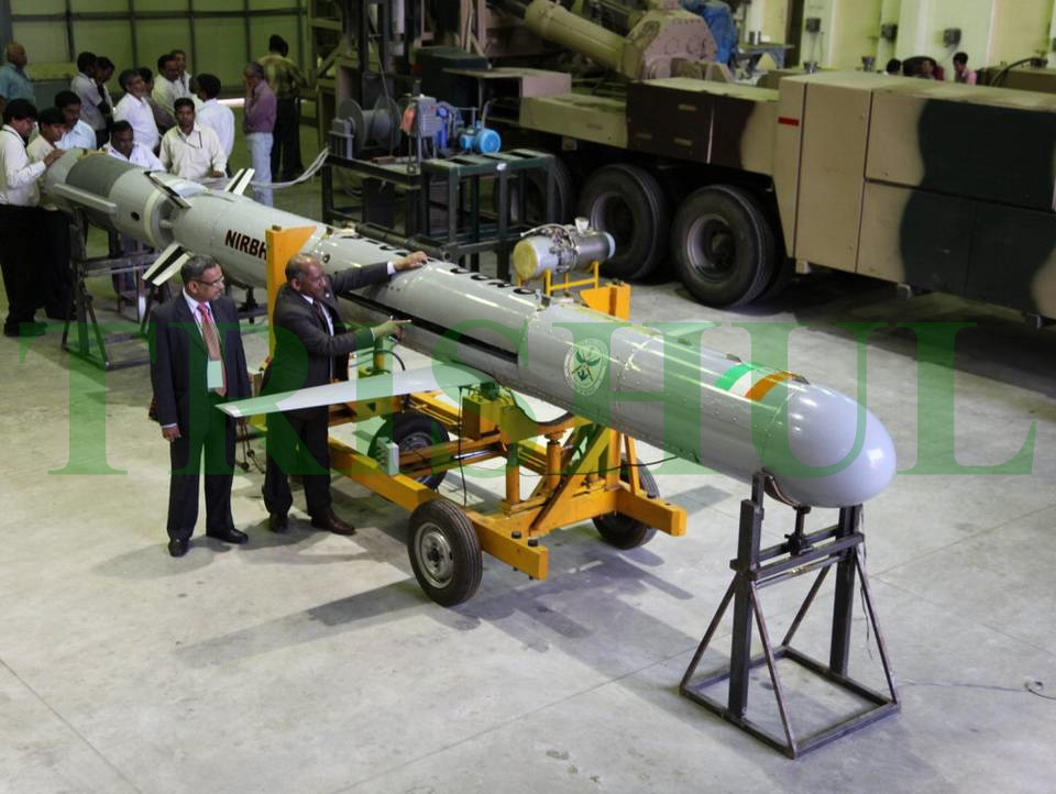
Nirbhay
LACM Explained
The Nirbhay is a subsonic LACM designed
to fly at subsonic speeds to neutralise targets of interest deep inside the
adversary’s territory in the early days of a conflict. This project was
conceived back in 2003 as a ground-launched cruise missile (GLCM) and
air-launched cruise missile (ALCM) for the Indian Air Force (IAF) and as a
warship-launched/submarine-launched cruise missile (SLCM) for the Indian Navy
(IN). An inter-governmental agreement inked in mid-2005 between India and
Russia saw the formalisation of industrial partnerships between India’s Defence
Research & Development Organisation’s (DRDO) Bengaluru-based Aeronautical
Development Establishment (ADE) and Russia’s Novator OKB, and between India’s
Hindustan Aeronautics Ltd (HAL) and Russian engine manufacturer JSC NPO Saturn.
Subsequently, Novator OKB transferred the design data package of its 3M-14E
LACM to ADE for re-engineering purposes, while JSC NPO Saturn began shipping 12
fully-assembled and ready-to-install 37-01E turbofans for the Nirbhay’s
flight-test programme, and this was to be followed by the supply of an
additional 600 turbofans in knocked-down condition to HAL for final assembly. Full-scale
prototype development work commenced in early 2007, with the ADE being
designated as the nodal systems house for R & D along with ASL (Hyderabad),
RCI (Hyderabad), HEMRL (Pune), R & DE (E) (Pune), TBRL (Chandigarh), ITR
(Balasore) and GTRE (Bengaluru) as sub-systems re-engineering partners. Phase-I
of the project focussed on the development of Nirbhay’s ground-launched version.

Any cruise missile mission consists of
pre-launch, launch, cruise and terminal phase. The pre-launch mission phase deals
with mission planning, waypoint selection, on-board mission computer’s
algorithm, complete missile system checkout, and the fire-control system. The
launch phase starts with booster fire and shaping the trajectory with the help
of thrust vectoring and ends with a configuration suitable for cruise phase.
The cruise missile configuration is basically an aircraft-like configuration
that flies along the various waypoints using autonomous waypoint navigation. At
the end of the cruise phase, the missile performs a terminal manoeuvre to home
to a target at the desired attack angle.

The unique selling point of the LACM
includes:
•
Long-range missions at very low altitudes
•
Autonomous mission and trajectory control through waypoint navigation
•
High degree of loitering capability
•
High degree of range scalability
•
Deployable from multiple platforms
•
Designed to carry desired warheads on targets of interest
•
A cost-effective weapon delivery platform
•
Ability to attack the target from any desired direction

The Nirbhay is configured to achieve various
mission phase requirements. This bank-to-turn missile was designed with a low
wing and four all-moving fins for stability and control. The missile, designed
with a high degree of modularity, consists of seven sections to house the seeker,
warhead, on-board avionics, fuel and air-intake section for the turbofan engine,
and the expendable booster section. This configuration is optimised for low-altitude
flights though it delivers desired performance for the full flight envelope. The
airframe was designed by Novator OKB for modular fabrication and integration,
predominantly with light aluminium alloy and composite materials. The airframe
was designed considering the ‘g’ loads experienced in the boost and cruise
phases. The airframe construction uses glass-fibre and carbon-fibre as
reinforcements in fabric form, epoxy resin system as matrix, and acrylic foam
(Rohacell) is used as a core material. Fabrication uses wet layup, pre-pregs
and matched die-moulding process. The bulkheads and longerons are also made of
aluminium alloy. The structural sizing of the airframe was carried out to
satisfy strength, stiffness and stability criteria as well as dynamic and
aero-elastic requirements as stipulated in applicable aircraft standards and
military standards.

The Mobile Articulated Launcher is
configured for transportation, emplacement, erection, activation and the launching
of missiles. In addition, the launcher also houses the main and standby power-supply
systems, the fire-control and checkout system for up to four missiles,
intra-communication system for communications with the combat management system
and other associated ground-support systems equipment. The launcher is built
with a rail-guide, on which the missile-lugs travel to ensure safe clearance. The
current launcher, fabricated by Larsen & Toubro, is a prototype to be used
for development flights of the missile. The actual launcher will be developed
against specific requirements of the users. The Fire-Control & Checkout System
(FCCS) is intended for automatic checkout, preparation before launch and launch
of the missiles. The FCCS consists of a launch console, which is the central
controller that coordinates the activities of all the sub-systems. Interaction
of the launch complex with the articles is facilitated via the missile
interface unit. The launch complex can be also be operated from a remote
console. Mission planning is an essential activity and it deals with the collection
of relevant information on target, terrain, obstacles, threats, the missile’s
capability, and the ground-support capability to achieve maximum kill
probability.

The wing is folded and kept inside the
fuselage, held by the initial locking mechanism. The wing shutter opens during
the boost phase upon command and after the wing is deployed the door closing
mechanism is initiated to close the cut-out provided in the fuselage, resulting
in reduced missile drag during the cruise phase. The wing deployment systems is
attached to the centre bracket of the wing and an attachment bracket has been
welded with the fuel tank with a provision to fix a strut, which in turn
receives the wing centre bracket. The basic mechanism is of single slider crank-type.
The active force generated by a pair of pyro-cartridges is converted into
torque for rotating the wing through 90 degrees. Damper is provided in the
mechanism for energy absorption during deployment phase. The mechanism is
provided with two types of locking mechanism and stopper to keep the wing in
position after deployment. The submerged air-intake section consists of the
air-intake duct, which starts as a hole in the belly of the missile and guides
the air into the inlet section of the engine. The length, ramp angle and lip-radius
of the submerged air intake is designed to meet the constraints on distortion
levels and pressure recovery.

The requirements of long-range precision
navigation are achieved using redundant satellite-aided navigation system using
the IRNSS constellation. The primary navigation system is based on three sets
of ring laser gyro and accelerometers (supplied by Israel Aerospace Industries’
TAMAM Division), which produces unaided and aided navigation information at
regular intervals through a MIL-STD-1553B digital avionics databus. The
secondary navigation system is based on three sets of MEMS gyroscopes and
accelerometers that produce similar information as that of the primary
navigation system. In case of failure of on-board inertial sensors, the primary
navigation system uses equivalent information from the standby system till the
second failure. Upon second failure, the on-board control system uses the
secondary navigation system’s information for its control loop closure. The
redundant navigation systems ensure the desired nautical mile per hour accuracy
at the start of the missile’s terminal cruise phase. The primary launch phase
requirement of any cruise missile is to launch vertically through the mobile
articulated launcher and to align at any desired direction, meeting the
altitude and Mach number constraints at various instants of time. In this
phase, the missile transcends four configurations, starting with missile then
to a bomb (with fins only) and to a glider with wings deployed and finally an
aircraft configuration powered by the turbofan.

Accelerating the missile from
zero speed to the desired speed is achieved by using an expendable solid
propulsion booster, housed as a part of the booster section. This section is
connected to the main missile using four pyro-bolts, which are initiated for
stage separation after booster burn-out during launch. This section houses all
the onboard systems essential for thrust vectoring and also a separation mechanism
to ensure positive separation of the missile. The booster’s thrust axis is
deflected as desired by the thrust-vector control system to generate necessary
control forces to achieve the desired launch phase trajectory from vertical to horizontal.
The thrust-vector control systems consist of a pair of actuators mounted on a
flex-nozzle system to orient the thrust axis in both pitch and yaw planes. The
on-board control system compares the state information as measured by the on-board
inertial navigation system with desired trajectory, and generates steering commands
to the thrust-vector control actuator.
When the missile reaches the desired
speed and orientation, the solid propulsion booster is jettisoned using pyro-bolts
and retro-motors. The pyro-bolts ensure physical separation of the booster
section from the missile and the retro-motors ensure positive separation from
the missile. In this phase, the missile is entering the no-thrust zone and it
continues till the engine develops full thrust. After sufficient time
separation, the wing is unlocked, deployed and locked into its final desired position
that turns the missile to a glider configuration. In this phase, the missile is
still in the no-thrust zone. After sufficient time separation, the turbofan is
started in-flight, which turns the missile into powered aircraft configuration.

When the turbofan develops the full thrust, the missile exits the no-thrust
zone and enters into an unmanned vehicle configuration. The missile is designed
to execute the mission autonomously without any external intervention and it
also has the ability to reconfigure the flight-control system’s commands in
response to different on-board events and failures. The FCSS uses body rates,
liner accelerations, attitudes and positions obtained from the RLG-INS for all
control loops. Baro-altitude obtained from an air data sensor is used by the navigation
system for vertical channel damping and a radar altimeter is used exclusively
for low-altitude flights. The four linear fin-actuators are located around the
turbofan in a narrow annular space. The desired stability and control of the
missile in the cruise phase is achieved using four fin actuators and are individually
commanded by the flight-control computer (FCC).

The FCC is the prime
computational hardware that performs the main functions of flight and mission control
such as sensor data acquisition, sensor computation, longitudinal, lateral and
directional control law execution, and provides the drive signals for on-board
discrete events and actuators through 1553B and RS422 databuses. All the
flight-control laws, mission control laws and safety logics are coded in strict
adherence to DoD-STD-2167A and implemented in the FCC. The cruise phase
capabilities of the missile are achieved through autonomous waypoint
navigation. In this mode, the missile exhibits its capability to control the trajectory
in vertical and horizontal planes while maintaining the desired track. Also,
this system is designed with no restriction on the heading change between the
waypoints.

The maiden launch of Nirbhay LACM’s
ground-launched version was conducted on March 12, 2013 during which it flew
for 20 minutes and thereafter deviated from its flight path due to a failure of
the on-board MEMS gyroscopes and accelerometers, and consequently its on-board
self-destruct mechanism was activated. The second launch was conducted on October
17, 2014 at ITR, Chandipur, and was a big success, with the LACM travelling
1,010km instead of the targetted 800km.These two launches demonstrated several
new indigenously-built technologies like automated pre-launch checks,
booster-assisted launch phase trajectory control, stage separation in
near-horizontal attitude, in-flight wing deployment, submerged air intake for
engine and in-flight engine start. The repeatability of these achievements has
demonstrated the systematic approach and robustness of the design.

The second
launch also demonstrated complete autonomous mission mode, comprising of cruise
phase based on waypoint navigation and the terminal phase. The third test-flight
on October 16, 2015 was again a failure. After 70 seconds of its flight, the
missile lost control and fell within the safety zone. The fourth flight-test on
December 21, 2016 was an utter failure, caused by a wing-deployment problem.
After liftoff, the missile started veering dangerously towards one side in less
than two minutes. The missile started flying beyond the safety corridor and
threatened to fall on the land. So the “destruct” mechanism in its first stage
was activated and the LACM was destroyed. It was undoubtedly a hardware failure
due to a reliability issue with a component.


BrahMos-NG
Explained
BrahMos Aerospace Ltd was established in
India through an inter-governmental agreement signed on February 12, 1998
between Russia and India. The DRDO from India and JSC MIC NPO Mashinostroyenia
(NPOM) from Russia are the joint venture partners of BrahMos Aerospace, which
was started with a capital of US$250 million with 50.5% from the Indian side
and 49.5% from the Russian side. JSC
MIC Mashinostroyenia comprises eight strategic companies: NPO Mashinostroyenia
(Reutov, Moscow), JSC Production
Association Strela (Orenburg), JSC
Permsky Zavod Mashinostroitel (Perm), JSC
Scientific and Production Association of Electro-Mechanic and JSC Makeyev State Rocket Center SKB-385 (Miass,
Chelyabinsk), FSUE Avangard (Safonovo, Smolensk),
FSUE Ural Research Institute of Composite Materials, or UNIIKM (Perm), NII
Electromechaniki (Istra, Moscow) and Concern Granit-Electron (St Petersburg).

Unlike the ground-launched/ship-launched
BrahMos-1 and its air-launched BrahMos-A version that can be carried only by
the Su-30MKI H-MRCA, the BrahMos-NG (known earlier as BrahMos-Mini) will be
lighter and narrower, enabling it to be launched by M-MRCAs like the Rafale,
MiG-29UPG and carrier-based MiG-29Ks, and it will also be capable of being
launched from a submarine’s 533mm torpedo-tubes.

The entire on-board avionics suite of
the BrahMos-NG—which will have a high degree of communality with that on-board
the Nirbhay family of LACMs—will be of Indian origin and it is now under
development via the cluster of public-sector and private-sector industrial
entities that are also involved with the Nirbhay’s developmental effort.

The
SAAW Explained
The SAAW is a joint India-Israel project
to co-develop an air-launched, standoff EMP-emitting missile, which, for all
intents and purposes, will be India’s first operational precision-guided
directed-energy weapon (DEW). It may be recalled that in the night of September
6, 2007 in the desert at Al Kibar, 130km (81 miles) from the Iraqi border and
30km from the northern Syrian provincial city Deir el-Zor, a fleet of ten
IDF-AF F-15Is conducted OP Orchard, which involved the
destruction of a heavy-water reactor then under construction with North Korean
expertise and Iranian funding. In that raid, the IDF-AF had used a
RAFAEL-developed precision-guided, standoff DEW to shut down Syria’s
ground-based air-defence sensors—a move that would go on to be the optimum
model for future surgical air-strikes.

Israel offered to
co-develop a variant of this DEW with India on July 7, 2008 during an official
meeting in Pune with the DRDO. This was followed by two additional meetings
held in Delhi with senior DRDO and IAF officials in August and September 2007.
The joint R & D project officially began in mid-2010 and series-production
of this DEW will commence later this year, with Indian industrial entities like
Bharat Dynamics Ltd, ECIL and the Kalyani Group being involved in this
undertaking. This air-launched, fire-and-forget,
expendable DEW, whose main role is to render electronic targets useless, makes
use of the airframe of RAFAEL’s Spice 250 rocket-powered PGM, and will have a
range of 120km. It is a non-kinetic alternative to traditional explosive
weapons that use the energy of motion to defeat their targets. During a
mission, this missile will navigate a pre-programmed flight plan (using
fibre-optic gyros) and at pre-set coordinates an
internal active phased-array microwave
emitter will emit bursts of selective high-frequency radio wave strikes
against up to six different targets during a single mission. The EMP-like field that will be generated will shut down all
hostile electronics. Thus, the whole idea behind such a weapon is to be able to
destroy an enemy’s command, control, communication and computing, surveillance
and intelligence (C4SI) capabilities without doing any damage to the people or
traditional infrastructure in and around it. In other words, it can eliminate a
hierarchical air-defence network’s effectiveness by destroying the electronics
within it alone, via a microwave pulse, without kinetically attacking the
network itself.

For the IAF, this air-launched DEW will
be a ‘first day of war’ standoff weapon that can be launched outside an enemy’s
area-denial/anti-access capabilities, and fly a route over known C4SI
facilities, zapping them along its way, before destroying itself at the end of
its mission. Because of its stealthy design, long-range and expendability, it
will fly where no other manned airborne assets could and because it does not
blow anything up, its use does not necessarily give away the fact that the
enemy is under direct attack in the first place. In that sense, it is also a
psychological weapon, capable of at least partially blinding an enemy before it
even knows that a larger-scale air-attack is coming. The IAF plans to arm its
upgraded Mirage 2000Hs, Jaguar IS/DARIN-3 interdictors and the
yet-to-be-delivered Rafale M-MRCAs with this DEW and also with RAFAEL’s
Spice-1000 PGMs. Unguided test-launches of the SAAW from a Jaguar IS were first
conducted at Pokhran in May 2015 to validate the weapons release/pylon ejection
mechanisms, while the first powered test-flight was conducted on December 23,
2016. Both the IAF and IN have a stated requirement for 500 SAAWs.


